





Key ideas
- Simple machines exchange force and distance or change the direction of a force; they do not create energy, and real losses depend, among other factors, on friction and deformation.
- Levers, pulleys, transmissions, and linkage mechanisms are distinguished by how they modify forces, transmit rotation, or convert rotation into displacement and reciprocating motion.
- The calculations presented are ideal and illustrative; classroom models make it possible to observe motion, but do not determine real load capacities.
Changing Forces and Motion Without Creating Energy
A simple machine can change the direction of a force or exchange force for distance. It does not produce energy: if less force is needed under ideal conditions, that force must act over a greater distance. Conversely, achieving more distance or speed at the output may require more force at the input. The ratio between output force and applied force is called mechanical advantage.
This exchange can be understood through work: a force acting while something moves transfers energy. In an ideal model, there are no losses, and input work equals output work. In a real machine, some energy is dissipated through friction or deformation; the weight of the parts also matters. For this reason, a ratio calculated using ideal geometry is not equivalent to a real load capacity.
Levers: Fulcrum, Force, and Resistance
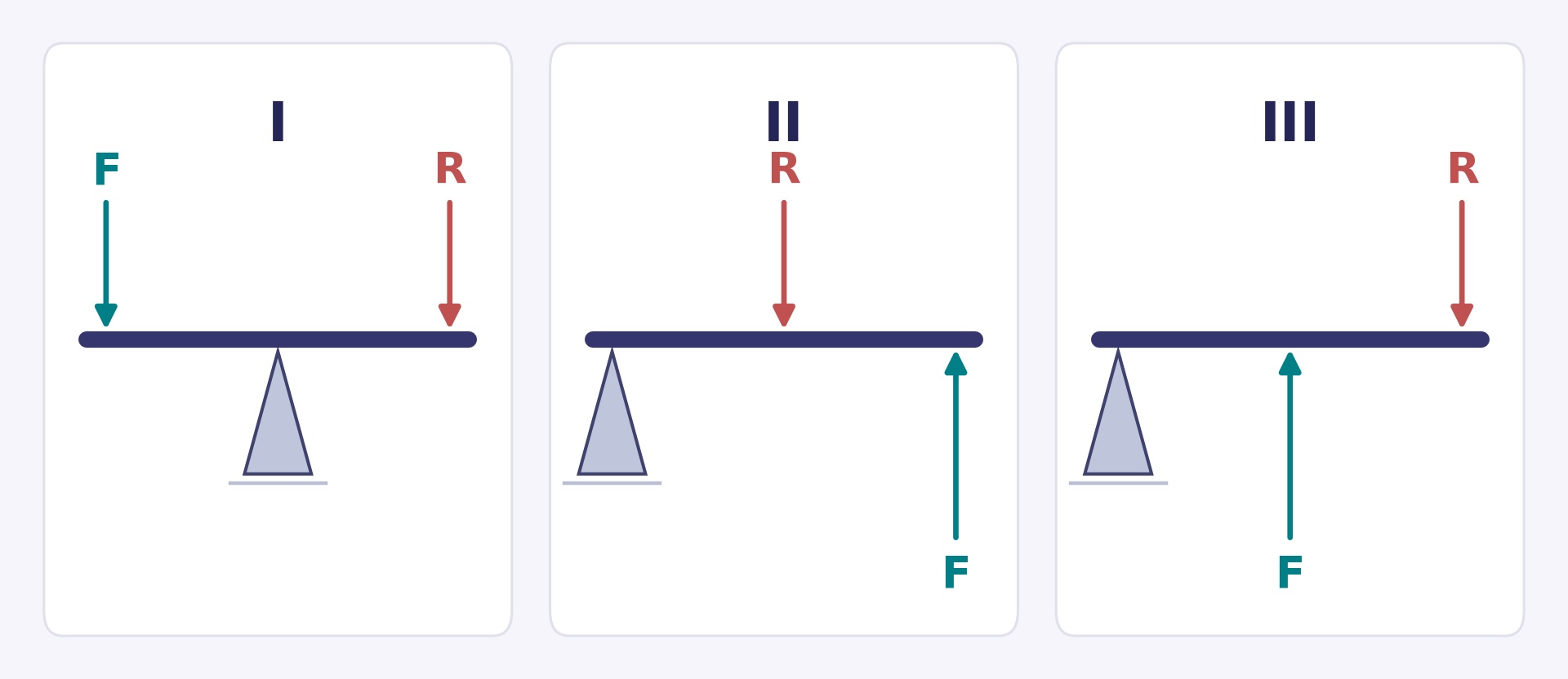
A lever is a bar that rotates around a support or fulcrum. In the diagrams, F is the applied force, R the resistance or load, and △ the fulcrum. Lever arms are not simply distances along the bar: they are the perpendicular distances from the fulcrum to the forces' lines of action. Diagrams I, II, and III show the relative positions and directions of F and R; they do not represent the magnitudes of the forces to scale, nor do they necessarily show all the reactions at the fulcrum. Therefore, their graphical proportions do not have to match those in the numerical example.
The three classes are distinguished by the order of these elements:
- I: F—△—R. The fulcrum lies between the force and resistance; examples: seesaw and scissors.
- II: △—R—F. The resistance lies between the fulcrum and force; examples: wheelbarrow and nutcracker.
- III: △—F—R. The force lies between the fulcrum and resistance; tweezers are one example.
A first-class lever can favor force or distance, depending on the length of the arms: it does not always multiply force. A second-class lever can provide a force advantage; a third-class lever usually favors the distance traveled by the output end, at the cost of a lower force advantage.
In equilibrium, the moments on both sides of the fulcrum are equal. If the forces are perpendicular to the bar and its weight and friction are ignored, 20 N applied at 0.60 m can balance 60 N at 0.20 m: 20 × 0.60 = 60 × 0.20 = 12 N·m. The force advantage is 60/20 = 3. This is a hypothetical calculated example, not a measurement or a safe-load recommendation. N means newton, a unit of force; it is not a mass in kilograms.
Pulleys and Winches: Changing Direction or Distributing Effort
An ideal fixed pulley changes the direction of the force but does not reduce its magnitude: its mechanical advantage is 1. An ideal movable pulley, supported by two equal vertical segments of the same rope, requires half the force to support the load, but twice as much rope must be pulled in to raise it the same distance.
In a block and tackle, count the rope segments supporting the movable block, not the wheels. This interpretation assumes an ideal rope, frictionless pulleys, and suitable geometry; it cannot be used to infer a real lifting capacity. A crane can combine pulleys with a winch: the crank turns a drum that winds up rope. If the crank radius is large compared with the drum radius, the force required is reduced, in exchange for a greater distance traveled by the hand.
Ramps, Wedges, and Screws
An inclined plane makes it possible to reach a height by following a longer path; a ramp makes ascent easier by spreading the change in height over that distance. A wedge can be understood as one or two inclined planes that, when moved, separate or adjust parts; a doorstop is a simple example.
A screw is a helix based on the inclined plane. When turned, it can produce relative axial movement between the screw and a nut that does not rotate. How far it advances depends on the helix design: one turn does not mean the same displacement for every screw. Do not assume that any screw or mechanism locks on its own.
Transmissions: Carrying Rotation from One Part to Another
Circular transmissions carry rotation between components. In external friction wheels, the surfaces in contact rotate in opposite directions; they can slip, in which case the geometric ratio no longer exactly describes the actual speed. An open belt makes pulleys rotate in the same direction, while a crossed belt reverses the direction. External gears also rotate in opposite directions. An open chain and its toothed sprockets rotate in the same direction; the teeth prevent the slipping associated with a smooth belt, provided the chain meshes correctly.
To compare speeds, the transmission ratio is defined here as i = output speed / input speed, using magnitudes; the direction of rotation is described separately. For two compatible gears or two sprockets connected by a chain, i = input teeth / output teeth. For pulleys or friction wheels without slipping, i = effective input diameter / effective output diameter. “Effective” refers to the contact or pitch diameter, not necessarily the outer edge. If i is less than 1, the output reduces speed; if it is greater than 1, it increases speed; if it is 1, speed is maintained. Some manuals use the reciprocal, so check the definition before interpreting a value.
For example, a 15-tooth driving gear that drives a 45-tooth gear has i = 15/45 = 1/3. With an input speed of 60 rpm, the ideal output is 20 rpm. If the gears are reversed, i = 45/15 = 3; with the same input of 60 rpm, the ideal output is 180 rpm. These are calculated examples, not test results. A reducer can increase torque by reducing speed, but it does not increase power for free. A worm and wheel also transmit rotation between shafts; they can provide a large reduction depending on the design, but should not be assumed to always act as a brake or be self-locking. The ordinary rule of counting the teeth of two gears to calculate their ratio does not apply here.
Converting Rotation into Displacement or Reciprocating Motion
A rack and pinion converts rotation into linear displacement, as in the movement of a platform or a steering system. In a connecting rod and crank, a rotating crank is joined to a hinged connecting rod that pushes and pulls a guided slider: this transforms rotation into reciprocating motion, or can transmit motion in the reverse direction, depending on the setup. The guide is what forces the slider to follow a straight path; a connecting rod alone does not guarantee straight-line translation.
A cam transmits motion through its profile: as it rotates, it can raise, pause, or lower a follower. The follower must be kept in contact using a solution appropriate to the setup, such as a guide, a spring, or gravity. An eccentric is a circular disk whose axis is offset from its geometric center; as it rotates, it can produce reciprocating motion. The profile and setup determine the motion, so not every cam is oval-shaped or produces the same cycle.
A crankshaft combines several cranks fixed together on a shaft. Together with connecting rods, it relates the reciprocating motion of pistons to rotation, as in certain mechanisms in reciprocating engines; not all engines or clocks have a crankshaft. Mechanical clocks, on the other hand, may contain gear trains.
Observing Mechanisms with Classroom Models
Using a ruler resting on a fulcrum and light loads, students can try different positions for F and R. Before moving them, it is useful to predict which arrangement will require more force and which end will travel farther; then, the positions can be varied and the changes recorded in a sketch.
Using small pulleys or spools and rope, the group can count the rope segments supporting the load and compare how much rope is pulled with how far the load rises. A paper or cardboard automaton with a cam, or a disk connected to a connecting rod and slider, makes it possible to observe how rotation is converted into rising and lowering or reciprocating motion. The profile or positions of the parts can be varied, and predictions and observations recorded, without attributing measured educational outcomes to the activity.
For safety, an adult should prepare cuts and holes. Avoid exposed points and pinch hazards, use very light loads, and do not use motors or mains electricity. These models are not suitable for assessing a crane's strength, lifting people, or determining real load capacities.
Summary Table of Machines and Mechanisms
| Mechanism | Type of motion / effect | Example |
|---|---|---|
| Lever | Changes the relationship between force and distance; can change direction | Seesaw, wheelbarrow, tweezers |
| Fixed pulley | Wheel rotation and change in the direction of the force | Crane pulley |
| Movable pulley | Ideally reduces force and increases the distance of rope traveled | Lifting system |
| Block and tackle | Distributes the effort among the rope segments supporting the movable block | Crane rigging |
| Winch | Turning the crank winds rope onto a drum | Lifting drum |
| Inclined plane | Increases the distance traveled to reach a height | Ramp |
| Wedge | Movement that separates or adjusts | Doorstop |
| Screw | Rotation → relative axial movement between screw and nut; the nut does not rotate in the case described | Screw and nut |
| Friction wheels | Transmit rotation through contact; can slip | Two wheels in contact |
| Pulleys and belt | Transmit rotation; direction depends on whether the belt is open or crossed | Belt drive |
| External gears | Transmit rotation in opposite directions and change speed | Gearbox; mechanical clock |
| Chain and sprockets | Transmit rotation between toothed sprockets | Bicycle drive |
| Worm and wheel | Transmit rotation between shafts and can reduce speed depending on the design | Transmission mechanism |
| Rack and pinion | Converts rotation into linear displacement | Steering or moving platform |
| Connecting rod and crank | Converts rotation into reciprocating motion through a guided slider, or vice versa | Piston mechanism |
| Cam and eccentric | Convert rotation into movement of a follower, depending on the profile and setup | Toy or automaton |
| Crankshaft | Relates the reciprocating motion of pistons to rotation through cranks and connecting rods | Reciprocating engine |
What we know and its limits
The ratios and numerical examples are described for ideal models or specified geometric conditions. In real mechanisms, friction, slippage, deformation, weight, and design affect behavior; the guide does not establish efficiencies or real load capacities. The transmission ratio is defined here as output speed divided by input speed, although some manuals use the reciprocal convention.
Original sources12
The original sources for exploring this explanation and its limits.
-
Simple Machines — Physics, 9.3
OpenStax — Rice University
Work, mechanical advantage, pulleys, wheel and axle, and families of simple machines. -
Simple Machines — College Physics, 9.5
OpenStax — Rice University
Lever equilibrium, perpendicular arms, and limits of the ideal model. -
Levers That Lift
TeachEngineering — University of Colorado Boulder
Three classes of levers and observation and comparison activities. -
Mechanisms and Simple Machines
Carnegie Mellon University — Yi Zhang, Susan Finger and Stephannie Behrens
Machine models, inclined plane, wheel and axle, gears, and belt. -
Gears — Introduction to Mechanisms
Carnegie Mellon University — Yi Zhang, Susan Finger and Stephannie Behrens
Gears, rack and pinion, worm gear, and speed ratio. -
Planar Linkages — Introduction to Mechanisms
Carnegie Mellon University — Yi Zhang, Susan Finger and Stephannie Behrens
Connecting rod and crank, slider, and reciprocating motion. -
Cams — Introduction to Mechanisms
Carnegie Mellon University — Yi Zhang, Susan Finger and Stephannie Behrens
Cams, followers, profiles, and the need to maintain contact. -
Friction wheels — Mechanisms
Xunta de Galicia — recursos educativos de Tecnología
Wheels in contact, slippage, diameter, and direction of rotation. -
Chains — Mechanisms
Xunta de Galicia — recursos educativos de Tecnología
Chain and sprockets, ratios, and applications such as bicycles. -
Cam and eccentric — Mechanisms
Xunta de Galicia — recursos educativos de Tecnología
Distinguishing between a profiled cam and an eccentric disk with an offset shaft. -
Crankshaft — Mechanisms
Xunta de Galicia — recursos educativos de Tecnología
Cranks joined together and conversion between piston motion and rotation. -
Cardboard Automata
Exploratorium — Tinkering Studio
Museum guide to exploring cams, levers, and connecting rods through automata.
Image credits
Editorial Team · original educational diagram · Original source · Recurso editorial propio · derechos reservados · Original vector drawing, exported as JPEG for web viewing. Positions and directions of forces F and R; arrow lengths are not proportional to magnitudes; the fulcrum reaction and the weight of the bar are omitted.